Posts mit dem Label vrf werden angezeigt. Alle Posts anzeigen

Montag, 14. Dezember 2009

DE - dynamisches Routeleanking oder "Inter VRF routing"

Dynamisches Route Leaking oder Routing Protokolle fürs Routing zwischen der globales Routingtabelle (GRT) und VRFs

Hallo zusammen,

das letzte mal gab es ein Beispiel, wie man statisch das Routing zwischen 2 VRFs einrichtet und dachte, daß es doch garnicht so schwer sein kann, dies auch dynamisch zu realisieren ... das war reichlich naiv ;)
Nach massig herumprobieren und mit dem Rat von ein paar anderen habe ich ein kleines Lab zusammengebaut, wo Routen zwischen der GRT und einem VRF dynamisch ausgetauscht werden.
Soweit ich es sagen kann, gibt es keine Möglichkeit Routen auf normalem Wege zu redistributen, wenn ein Routingprozess der globale ist. Wenn man es dennoch versucht, bekommt man eine kryptische Fehlermeldung wie diese:
VRF -> GRT [code]%OSPF process 1 is attached to Default-IP-Routing-Table[/code]
GRT -> VRF [code]OSPF process 22 already exists and is attached to Default-IP-Routing-Table[/code]

Dies müssen wir einfach "austricksen" und dafür brauchen wir einige Tunnelinterfaces und ein paar Loopbacks

So sieht mein Netzplan aus:


Der globale Client und der VRF_Client werden wieder durch missbrauchte Router dargestellt, die lediglich eine IP haben und eine Default Router auf das ausgehende Interface+Next Hop IP.

grt_host
[code]interface FastEthernet0/0
ip address 10.10.10.10 255.255.255.0
ip route 0.0.0.0 0.0.0.0 10.10.10.1 FastEthernet0/0[/code]

vrf_host
[code]interface FastEthernet0/1
ip address 20.20.20.20 255.255.255.0
ip route 0.0.0.0 0.0.0.0 20.20.20.1 FastEthernet0/1[/code]

Nun brauchen wir ein paar Grundkonfigurationen für den VRF Router:

ein vrf erstellen:
ip vrf zif
rd 1:1
route-target both 1:1


Interface config zum grt_host:
interface FastEthernet0/0
ip address 10.10.10.1 255.255.255.0
speed 100
full-duplex


Interface config zum vrf_host:
interface FastEthernet0/1
ip vrf forwarding zif
ip address 20.20.20.1 255.255.255.0
speed 100
full-duplex


Das alles ist kein Hexenwerk ... bis jetzt ;)

Das erste was wir uns überlegen müssen: wie tricksen wir die Grenzen des Designs aus?

Die erste Zutat sind "Tunnel-Interfaces", die andere sind "Loopbacks".

Unterm Strich brauchen wir:
ein Tunnel-Interface pro VRF,
ein Tunnel-Interface für die GRT
ein Loopback pro VRF und
ein Loopback für die GRT.

Wenn wir mehrere VRFs mit der GRT verknüpfen wollen, brauchen wir entsprechend der obigen Liste das gleiche nochmal pro zusätlichem VRF.

Beide Loopbacks werden in der GRT gelassen:
VRF Router
interface Loopback111
ip address 111.111.111.111 255.255.255.255

interface Loopback222
ip address 222.222.222.222 255.255.255.255


Jetzt brauchen wir die dazugehörigen Tunnel-Interfaces.
Das für die GRT:
interface Tunnel102
ip address 100.100.100.1 255.255.255.0
tunnel source 111.111.111.111
tunnel destination 222.222.222.222

Und das für das VRF:
interface Tunnel201
ip vrf forwarding RED
ip address 100.100.100.2 255.255.255.0
tunnel source 222.222.222.222
tunnel destination 111.111.111.111


Was macht dieses Konstrukt? Wir zeigen mit dem dem Tunnel 201 auf die Loopback in der GRT, mit der Quelle in der GRT und packen das ganze dann ins VRF. Hört sich nicht nur komisch an, es ist komisch (und "fühlt sich komisch an), ABER es funktioniert ;)

Jetzt haben wir schicke Netzwerke, zwischen denen wir ein Routingprozess wie zB OSPF laufen lassen können.

Der globale Routingprozess:
router ospf 1
router-id 10.10.10.10
log-adjacency-changes
network 100.100.100.1 0.0.0.0 area 0
network 10.10.10.0 0.0.0.255 area 0


Der VRF Routingprozess:
router ospf 2 vrf zif
router-id 20.20.20.20
log-adjacency-changes
network 20.20.20.0 0.0.0.255 area 0
network 102.102.102.2 0.0.0.0 area 0


Die Routing Tabelle schaut danach wiefolgt aus::
global

VRF_Router#sh ip route
[...snip...]

Gateway of last resort is not set

102.0.0.0/24 is subnetted, 1 subnets
C 102.102.102.0 is directly connected, Tunnel102
200.200.200.0/32 is subnetted, 1 subnets
C 200.200.200.200 is directly connected, Loopback200
100.0.0.0/32 is subnetted, 1 subnets
C 100.100.100.100 is directly connected, Loopback100
20.0.0.0/24 is subnetted, 1 subnets
O 20.20.20.0 [110/11112] via 102.102.102.2, 00:24:29, Tunnel102
10.0.0.0/24 is subnetted, 1 subnets
C 10.10.10.0 is directly connected, FastEthernet0/0

vrf

Router#sh ip route vrf zif

Routing Table: zif
[...snip...]

Gateway of last resort is not set

102.0.0.0/24 is subnetted, 1 subnets
C 102.102.102.0 is directly connected, Tunnel201
20.0.0.0/24 is subnetted, 1 subnets
C 20.20.20.0 is directly connected, FastEthernet0/1
10.0.0.0/24 is subnetted, 1 subnets
O 10.10.10.0 [110/11112] via 102.102.102.1, 00:26:19, Tunnel201


Und das wars auch schon!
Nun ist es möglich vom grt_host direkt den vrf_host zu pingen und umgekehrt.

Bei Fragen nutzt einfach die Kommentarfunktion

Bis dann,
Zif
Mittwoch, 1. Juli 2009

EN - dynamic routleaking or Inter VRF routing

dynamic route leaking or routing protcols between global routing table (GRT) and VRFs

Hey Everybody,

last time I showed some exampel config for static roue leaking and thought that dynamic routing between GRT and VRF can't be that hard ... how green.
After some hard trys and help from other people I will now show you, how to exchange routes between GRT and VRF-RT dynamicly.
There is no chance to do a normal redistrubution between routing processes if one is the global one.
If you try so, you'll get some cryptic message like
VRF -> GRT [code]%OSPF process 1 is attached to Default-IP-Routing-Table[/code]
GRT -> VRF [code]OSPF process 22 already exists and is attached to Default-IP-Routing-Table[/code]

How ever, now we need to get this tricked. Therefor we use tunnel interfaces and some loopbacks.

This is my tiny topology:


The global Client and the VRF_Client are again just some as host missused routers with one IP address and a default route pointing on the outgoing IF.
grt_host
[code]interface FastEthernet0/0
ip address 10.10.10.10 255.255.255.0
ip route 0.0.0.0 0.0.0.0 10.10.10.1 FastEthernet0/0[/code]

vrf_host
[code]interface FastEthernet0/1
ip address 20.20.20.20 255.255.255.0
ip route 0.0.0.0 0.0.0.0 20.20.20.1 FastEthernet0/1[/code]

Now are some basic config for the vrf_router needed:

Create a vrf:
ip vrf zif
rd 1:1
route-target both 1:1


Link to grt_host:
interface FastEthernet0/0
ip address 10.10.10.1 255.255.255.0
speed 100
full-duplex


Link to vrf_host:
interface FastEthernet0/1
ip vrf forwarding zif
ip address 20.20.20.1 255.255.255.0
speed 100
full-duplex


This all was no rocket science yet, until now ;)

First thing to figure out: how to outsmart the limitations of design?

One credential are "Tunnel-Interfaces", an other one "loopbacks".

In sum we need one tunnel-IF per VRF and GRT plus one loopback for each.

Both loopbacks are left in GRT:
VRF Router
interface Loopback111
ip address 111.111.111.111 255.255.255.255

interface Loopback222
ip address 222.222.222.222 255.255.255.255


Now we need the correspondent tunnel IFs.
The global one:
interface Tunnel102
ip address 100.100.100.1 255.255.255.0
tunnel source 111.111.111.111
tunnel destination 222.222.222.222

And the VRF one:
interface Tunnel201
ip vrf forwarding RED
ip address 100.100.100.2 255.255.255.0
tunnel source 222.222.222.222
tunnel destination 111.111.111.111


What this is doing: pointing with the tunnel 201 to a GRT loopback with a source in GRT putting itself in a VRF. It sounds, strange, it looks strange, it feels strange, BUT it works ;)

Now you have sweet networks which you can add to routing processes like OSPF.

The global routing process:
router ospf 1
router-id 10.10.10.10
log-adjacency-changes
network 100.100.100.1 0.0.0.0 area 0
network 10.10.10.0 0.0.0.255 area 0


The VRF routing process:
router ospf 2 vrf zif
router-id 20.20.20.20
log-adjacency-changes
network 20.20.20.0 0.0.0.255 area 0
network 102.102.102.2 0.0.0.0 area 0


The routintg tables looks like this:
global

VRF_Router#sh ip route
[...snip...]

Gateway of last resort is not set

102.0.0.0/24 is subnetted, 1 subnets
C 102.102.102.0 is directly connected, Tunnel102
200.200.200.0/32 is subnetted, 1 subnets
C 200.200.200.200 is directly connected, Loopback200
100.0.0.0/32 is subnetted, 1 subnets
C 100.100.100.100 is directly connected, Loopback100
20.0.0.0/24 is subnetted, 1 subnets
O 20.20.20.0 [110/11112] via 102.102.102.2, 00:24:29, Tunnel102
10.0.0.0/24 is subnetted, 1 subnets
C 10.10.10.0 is directly connected, FastEthernet0/0

vrf

Router#sh ip route vrf zif

Routing Table: zif
[...snip...]

Gateway of last resort is not set

102.0.0.0/24 is subnetted, 1 subnets
C 102.102.102.0 is directly connected, Tunnel201
20.0.0.0/24 is subnetted, 1 subnets
C 20.20.20.0 is directly connected, FastEthernet0/1
10.0.0.0/24 is subnetted, 1 subnets
O 10.10.10.0 [110/11112] via 102.102.102.1, 00:26:19, Tunnel201


And thats it! Now you are able to ping from you grt_host straight through the vrf_host.

For questions just use the comments.

so long,
Zif

Mittwoch, 29. April 2009

EN - "Route Leaking" or Inter VRF routing

Heyho,

today I want to give a small guide, how to configure inter-VRF (VRF = VPN Routung and Forwarding) routing.
The Cisco documentation I found for this is more likely rocket science than a working guide.

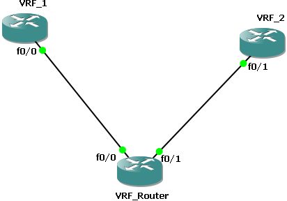
The task was to implement static routes on one device routing between different VRFs.
I used following network map:

Both routers "VRF_1" and "VRF_2" are only hosts with only an IP and a default route pointing at the outgoin interface:
VRF1
interface FastEthernet0/1
description Link to VRF_Router
ip address 10.0.100.2 255.255.255.0
speed 100
full-duplex
!
ip route 0.0.0.0 0.0.0.0 FastEthernet0/0

VRF2
interface FastEthernet0/1
description Link to VRF_Router
ip address 10.0.200.2 255.255.255.0
speed 100
full-duplex
!
ip route 0.0.0.0 0.0.0.0 FastEthernet0/1


Now to the routing part:
At first you need an basic VRF lite config:
ip vrf vrf1
rd 1:1
route-target export 1:1
route-target import 1:1
!
ip vrf vrf2
rd 2:2
route-target export 2:2
route-target import 2:2

The two commands route-target export 2:2 and route-target import 2:2 can be summed up with the command "route-target both. In your config this will be automaticaly replaced with to commands shown.

In addition to this there is some IF configuration:
interface FastEthernet0/0
ip vrf forwarding vrf1
ip address 10.0.100.1 255.255.255.0
speed 100
full-duplex
!
interface FastEthernet0/1
ip vrf forwarding vrf2
ip address 10.0.200.1 255.255.255.0
speed 100
full-duplex


The command ip vrf forwarding [vrf_name] associates the IF into a VRF so the traffic is marked up.

Now you need to set up the routing. There for you only need a route for each VRF pointing on the IF and Next-Hop-IP of the targeted VRF.
ip route vrf vrf1 10.0.200.0 255.255.255.0 FastEthernet0/1 10.0.200.2

ip route vrf vrf2 10.0.100.0 255.255.255.0 FastEthernet0/0 10.0.100.2


And thats all. If you issue the command show ip route.
VRF_Router#show ip route
Codes: C - connected, S - static, R - RIP, M - mobile, B - BGP
D - EIGRP, EX - EIGRP external, O - OSPF, IA - OSPF inter area
N1 - OSPF NSSA external type 1, N2 - OSPF NSSA external type 2
E1 - OSPF external type 1, E2 - OSPF external type 2
i - IS-IS, su - IS-IS summary, L1 - IS-IS level-1, L2 - IS-IS level-2
ia - IS-IS inter area, * - candidate default, U - per-user static route
o - ODR, P - periodic downloaded static route

Gateway of last resort is not set

VRF_Router#

You'll see an empty global routing table. If you add show ip route vrf [vrf_name]. As example only the output of one vrf:
VRF_Router#show ip route vrf vrf1

Routing Table: vrf1

[... snip ...]

Gateway of last resort is not set

10.0.0.0/24 is subnetted, 2 subnets
C 10.0.100.0 is directly connected, FastEthernet0/0
S 10.0.200.0 [1/0] via 10.0.200.2, FastEthernet0/1
VRF_Router#

Note that it says explictly which routing table it's showing you and you have one extra routing table for each VRF.


If there are any open questions left, just use the commenting funtion


Regrads,
Zif