Posts mit dem Label advanced werden angezeigt. Alle Posts anzeigen

Montag, 10. Oktober 2011

EN - HEv6 Tunnel improvements

After surfing the HE forum and a few other blogs I noticed some nice improvements that i would like to share with you.

DDNS URL
Currently I´m using the inital URL from HE but it is possible to use another URL that does not leave youre password in plaintext in your config

https://ipv4.tunnelbroker.net/ipv4_end.php?ip=AUTO&pass=MD5PASS&apikey=USERID&tid=TUNNELID

Keep in mind that USERID is not your accountname but the ID you can find on the HE webpage. MD5PASS is your account password as MD5 hash and TUNNELID stays your asigned tunnel id.
For the ip parameter you can either choose your static IPv4 IP or AUTO for dynamic IP updates.

Another interessting option is the following command

ipv6 general-prefix HEv6 2001:470:XXXX::/48

This enables you to use the reference your prefix by calling the “name” of the prefix. The configuration of the loop 2 interface changes accordingly to:

Interface loopback 2
ipv6 address HEv6 ::1/58
 ipv6 enable

Thanks to Karsten for the prefix hint on his blog. (Link)

DE - HEv6 Tunnel Verbesserungen


Nachdem ich noch etwas Zeit in den Foren von HE verbracht hab und auch bei anderen Quellen mich umgesehen habe, will ich hier noch ein paar Verbesserungen einpflegen.

DDNS URL
Derzeit verwende ich die URL wie sie Initial vorgeschlagen wird, aus dem HE Forum habe ich eine neue Form der URL, die verhindert dass das Passwort im Klartext in der Router Konfig steht.
  
https://ipv4.tunnelbroker.net/ipv4_end.php?ip=AUTO&pass=MD5PASS&apikey=USERID&tid=TUNNELID
 
Dabei ist zu beachten, das im Gegensatz zur original Form, ist der paramter IP mit der statischen IP oder mit AUTO für dynamische IPs zu belegen, sowie die USERID die ID und nicht der Accountname, MD5PASS das Accountpasswort als MD5 Hash und die TUNNELID wie gehabt die Tunnelid des IPv6 Tunnels ist.


Auch interessant ist die Option

Das ermöglicht das Referenzieren in der weiteren Routerkonfiguration auf diesen Präfix. Lässt sich einfacher merken und spricht sich im Zweifelsfall auch einfacher.

ipv6 general-prefix HEv6 2001:470:XXXX::/48

Daraus ergibt sich für das Loop 2 Interface folgende Config
nterface loopback 2
ipv6 address HEv6 ::1/58
 ipv6 enable

 Danke an Karsten bei dem ich mir das Präfix Command geliehen hab. (Link)

Sonntag, 9. Oktober 2011

EN - Hurricane Electric IPv6 Tunnel with Cisco 887


As mentioned earlier I was playing with the Hurricane Electric IPv6 Tunnel setup. Now that the Tunnel is up and running I would like to share some knowledge I gained and provide a few config sniplets.

Starting with the registration at www.tunnelbroker.net you can request an IPv6 Tunnel. As soon as you´ve registered you can set up your tunnel and register for a complete network with a/48 mask. Obviously to say – I did register for the network.

You can divide configuring your router into 4 steps (more or less)
  • Tunnel creation
  • Configure HE Tunnel update
  • Add the HE Certificate
  • Configure and use your /48 network
  • testing
The default configuration of HE expects you to have a static IPv4 configured at your router. Well since I’m using a home DSL connection my IP address changes every 24 hours. That´s why I change the tunnel source from IP to dialer 1. 

interface Tunnel0
 description Hurricane Electric IPv6 Tunnel Broker
 no ip address
 ipv6 enable
 ipv6 address 2001:470:xxxx:xxxx::2/64
 tunnel source Dialer 1
 tunnel destination 216.66.84.42
 tunnel mode ipv6ip
ipv6 route ::/0 Tunnel0
Additional to the configuration I added this interface into the appropriate zone of the Zone-Based firewall.
The next step for locations with changing IP addresses is to convince your router to tell HE the changing IPv4 address. Hurricane offers a default URL that you can use for the updating process.
https://ACCOUNTNAME:ACCOUNTPASSWORT@ipv4.tunnelbroker.net/ipv4_end.php?tid=TUNNELID

To update your IP at HE, you can use the DDNS feature of the Cisco router.

ip ddns update method HEv6
 HTTP
  add https://ACCOUNTNAME:ACCOUNTPASSWORT@ipv4.tunnelbroker.net/ipv4_end.php?tid=TUNNELID   !update in next blog post
 interval maximum 0 6 0 0
 interval minimum 0 1 0 0
Every hour but your router will update the IP at HE.
You have to update the configuration of your dialer interface (or the interface that is providing your internet connection) to update HE.
Interface Dialer 1
 ip ddns update hostname WS-Router
 ip ddns update HEv6
Next step is to import the certificate HE is using for the tunnel broker website. Since this page is using a self-signed certificate the update with ddns could cause problems if you don´t import it.
crypto pki trustpoint HEv6
 enrollment terminal pem
 revocation-check none
You need to authenticate the trustpoint using the following dialog:
#crypto pki authenticate HEv6

Enter the base 64 encoded CA certificate.
End with a blank line or the word "quit" on a line by itself

MIID8DCCAtigAwIBAgIJAPF6IlDmmdRhMA0GCSqGSIb3DQEBBQUAMIGcMQswCQYD
VQQGEwJVUzETMBEGA1UECBMKQ2FsaWZvcm5pYTEQMA4GA1UEBxMHRnJlbW9udDEg
MB4GA1UEChMXSHVycmljYW5lIEVsZWN0cmljLCBMTEMxDTALBgNVBAsTBElQdjYx
GTAXBgNVBAMTEHR1bm5lbGJyb2tlci5uZXQxGjAYBgkqhkiG9w0BCQEWC2lwdjZA
aGUubmV0MB4XDTExMDQyMjE3NDIyMFoXDTIxMDQxOTE3NDIyMFowgZwxCzAJBgNV
BAYTAlVTMRMwEQYDVQQIEwpDYWxpZm9ybmlhMRAwDgYDVQQHEwdGcmVtb250MSAw
HgYDVQQKExdIdXJyaWNhbmUgRWxlY3RyaWMsIExMQzENMAsGA1UECxMESVB2NjEZ
MBcGA1UEAxMQdHVubmVsYnJva2VyLm5ldDEaMBgGCSqGSIb3DQEJARYLaXB2NkBo
ZS5uZXQwggEiMA0GCSqGSIb3DQEBAQUAA4IBDwAwggEKAoIBAQDe5nza8zQ/AiT+
ySc4mZYmLMcIrcU3q6ZEwIY5vHg2chzCJGCPQIwtBiexSZ7CWL8/GjdPWs6DoCut
DS6VlGGaRhJd0ppUOB3uZLcqnfY0/d40WpRFm49yAV3fmhQg744BKUz2+V23E3tP
n4UXq507dQ3RmNiZoS/T+DUbt1URXFZDIJmc4vjnYfGQhUzhbWZbC7J5fMFnTFSL
NWNou4drWwcApm4FjPfVr+tdanjGEs8bMGSbXo6BjtStiEy1yJ3QGyZLwuURcMMv
DV06/hc2Nv9MZPUaIPvXmNcSuVvY3MJiD1CiCWVmfiO3h7b5EmIWC+ZpO9L3Mk6/
j/MgWR6jAgMBAAGjMzAxMC8GA1UdEQQoMCaCEHR1bm5lbGJyb2tlci5uZXSCEiou
dHVubmVsYnJva2VyLm5ldDANBgkqhkiG9w0BAQUFAAOCAQEAXMG5ZOeyRCzIEPYP
tZKbr1N0CkiBHf+7bVqUqfifEte6S/edpUdzIzB9Wtt484Dt88cAeg4BH2z+Kx2C
lE9PxtTSMCInZIniuoLhaBP0BiRXEurTYdreFmen/S5cCkffVr+eJGk92lQQAdMr
kyz2kD1NCwCaEp1w9DYltDbfC2v8BSIiEKVvD72VW6E2r7AvW73s3+E3WcWbt6pV
qrKfFH4mKH0BR7nLzm5zduojCvIdH3GjelyLd7lUVR3N8Dz626tOzni/bzHpbH3T
dMlBIl3f7c41wcoFG5zSZf1mvgyOnSlOnNmlxMbnfnrIyIyfYz1L8UWqWZGbxJYH
EXcOrA==

Certificate has the following attributes:
       Fingerprint MD5: 1128B641 08E7E271 B2FFB7FF 91411952
      Fingerprint SHA1: 9EB44F27 6BCE5EF6 5D9D38CC A9252276 4318075C

% Do you accept this certificate? [yes/no]: yes
Trustpoint CA certificate accepted.
% Certificate successfully imported

I exported the applied certificate from my browser after opening the tunnelbroker page with Firefox.

The /48 network HE assigned to me was subnetted and applied to my loop 2 interface to check if everything works fine.
Interface loopback 2
ipv6 address 2001:470:XXXX::1/58
 ipv6 enable
Last but not least you should activate domain lookups on your router to resolve the tunnelbroker URL for ddns.
Final testing:

ping ipv6 ipv6.google.com source loop 2
Sending 5, 100-byte ICMP Echos to 2A00:1450:8004::6A, timeout is 2 seconds:
Packet sent with a source address of 2001:470:XXX::1
!!!!!
Success rate is 100 percent (5/5), round-trip min/avg/max = 76/76/76 ms

YEAH! Everything worked as expected great ! 
More to come here!

DE - Hurricane Electric IPv6 Tunnel mit Cisco 887


Wie schon geschrieben hab ich mich das vergangene Wochenende mit dem IPv6 Tunnel von HE rumgeschlagen. Jetzt da er Up und Running ist will ich meine Erfahrungen mal zusammenfassen und Konfigsniplets preisgeben. 

Fangen wir am Anfang an, die Website ist unter www.tunnelbroker.net  zu finden, die Registrierung ist quasi selbsterklärend und sollte keine Hürde darstellen. Sobald man seinen Tunnel angelegt hat kann man sich auch noch ein Netz /48 reservieren lassen, was ich natürlich gleich gemacht hab. 

Die Konfiguration erfolgt in mehreren Schritten,
  • Tunnel aufsetzen
  • HE Tunnel update
  • HE Zertifikat einspielen
  •  /48 Netz verwenden
  • Test
Die Konfig des Tunnels geht davon aus, dass man eine statische IP hat und verwendet die IP des Browser in der initialen Konfiguration. Da wir nur einen Standard DSL am Standort haben hab ich die Statische IP durch das Dialer Interface ersetzt, das bei uns die DSL Einwahl macht.  

interface Tunnel0
   description Hurricane Electric IPv6 Tunnel Broker
   no ip address
   ipv6 enable
   ipv6 address 2001:470:xxxx:xxxx::2/64
   tunnel source Dialer 1
   tunnel destination 216.66.84.42
   tunnel mode ipv6ip
ipv6 route ::/0 Tunnel0

Zusätzlich hab ich das Interface noch in die entsprechende Zone der Zone-Base Firewall gehängt.

Als nächstes sollte man, bei dynamische angebundenen Standorten, den Router dazu überreden, bei Zwangstrennung oder IP wechseln die Tunneldaten bei HE zu aktualisieren.
Hurricane gibt dafür eine URL vor, die man vom Router aus aufrufen  kann, die URL hat folgenden Syntax:
https://ACCOUNTNAME:ACCOUNTPASSWORT@ipv4.tunnelbroker.net/ipv4_end.php?tid=TUNNELID

Um Hurricane zu aktualisieren sollte das DDNS feature des Routers verwendet werden:

ip ddns update method HEv6
 HTTP
  add https://ACCOUNTNAME:ACCOUNTPASSWORT@ipv4.tunnelbroker.net/ipv4_end.php?tid=TUNNELID !Update im nächsten Blogpost
 interval maximum 0 6 0 0
 interval minimum 0 1 0 0
Hier wird die dynamische IP meines Routers HE jede Stunde, spätestens nach 6 Stunden mitgeteilt.
 Dem Dialer Interface müssen noch die DDNS Infos mitgegeben werden, damit dieses HE aktualisiert.

Interface Dialer 1

 ip ddns update hostname WS-Router
 ip ddns update HEv6

Als letztes muss noch das Zertifikat von HE hinterlegt werden, da die Tunnelbroker Seite ein selbst signiertes Zertifikat verwendet und das zu Probleme mit dem DDNS Feature führen kann.
crypto pki trustpoint HEv6
 enrollment terminal pem
 revocation-check none
Danach muss der Trustpoint noch authentifiziert werden, der ganze Prozess stellt sich so dar:
crypto pki authenticate HEv6

Enter the base 64 encoded CA certificate.
End with a blank line or the word "quit" on a line by itself

MIID8DCCAtigAwIBAgIJAPF6IlDmmdRhMA0GCSqGSIb3DQEBBQUAMIGcMQswCQYD
VQQGEwJVUzETMBEGA1UECBMKQ2FsaWZvcm5pYTEQMA4GA1UEBxMHRnJlbW9udDEg
MB4GA1UEChMXSHVycmljYW5lIEVsZWN0cmljLCBMTEMxDTALBgNVBAsTBElQdjYx
GTAXBgNVBAMTEHR1bm5lbGJyb2tlci5uZXQxGjAYBgkqhkiG9w0BCQEWC2lwdjZA
aGUubmV0MB4XDTExMDQyMjE3NDIyMFoXDTIxMDQxOTE3NDIyMFowgZwxCzAJBgNV
BAYTAlVTMRMwEQYDVQQIEwpDYWxpZm9ybmlhMRAwDgYDVQQHEwdGcmVtb250MSAw
HgYDVQQKExdIdXJyaWNhbmUgRWxlY3RyaWMsIExMQzENMAsGA1UECxMESVB2NjEZ
MBcGA1UEAxMQdHVubmVsYnJva2VyLm5ldDEaMBgGCSqGSIb3DQEJARYLaXB2NkBo
ZS5uZXQwggEiMA0GCSqGSIb3DQEBAQUAA4IBDwAwggEKAoIBAQDe5nza8zQ/AiT+
ySc4mZYmLMcIrcU3q6ZEwIY5vHg2chzCJGCPQIwtBiexSZ7CWL8/GjdPWs6DoCut
DS6VlGGaRhJd0ppUOB3uZLcqnfY0/d40WpRFm49yAV3fmhQg744BKUz2+V23E3tP
n4UXq507dQ3RmNiZoS/T+DUbt1URXFZDIJmc4vjnYfGQhUzhbWZbC7J5fMFnTFSL
NWNou4drWwcApm4FjPfVr+tdanjGEs8bMGSbXo6BjtStiEy1yJ3QGyZLwuURcMMv
DV06/hc2Nv9MZPUaIPvXmNcSuVvY3MJiD1CiCWVmfiO3h7b5EmIWC+ZpO9L3Mk6/
j/MgWR6jAgMBAAGjMzAxMC8GA1UdEQQoMCaCEHR1bm5lbGJyb2tlci5uZXSCEiou
dHVubmVsYnJva2VyLm5ldDANBgkqhkiG9w0BAQUFAAOCAQEAXMG5ZOeyRCzIEPYP
tZKbr1N0CkiBHf+7bVqUqfifEte6S/edpUdzIzB9Wtt484Dt88cAeg4BH2z+Kx2C
lE9PxtTSMCInZIniuoLhaBP0BiRXEurTYdreFmen/S5cCkffVr+eJGk92lQQAdMr
kyz2kD1NCwCaEp1w9DYltDbfC2v8BSIiEKVvD72VW6E2r7AvW73s3+E3WcWbt6pV
qrKfFH4mKH0BR7nLzm5zduojCvIdH3GjelyLd7lUVR3N8Dz626tOzni/bzHpbH3T
dMlBIl3f7c41wcoFG5zSZf1mvgyOnSlOnNmlxMbnfnrIyIyfYz1L8UWqWZGbxJYH
EXcOrA==

Certificate has the following attributes:
       Fingerprint MD5: 1128B641 08E7E271 B2FFB7FF 91411952
      Fingerprint SHA1: 9EB44F27 6BCE5EF6 5D9D38CC A9252276 4318075C

% Do you accept this certificate? [yes/no]: yes
Trustpoint CA certificate accepted.
% Certificate successfully imported

Das eingefügte Zertifikat kann man aus den Browser exportieren, wenn man die DDNS URL manuell aufruft. 

Ich habe das /48 Netz etwas gesubnettet und verwende für den Test das Loop 2 Interface um von einfach zu schauen ob wir Konnektivität haben.

Interface loopback 2
ipv6 address 2001:470:XXXX::1/58
 ipv6 enable
Ach ja zu guter Letzt sofern noch nicht vorhanden, sollte DNS aktiviert sein, schon allein damit die DDNS URL von HE aufgelöst wird.
Abschließender Test:

ping ipv6 ipv6.google.com source loop 2
Sending 5, 100-byte ICMP Echos to 2A00:1450:8004::6A, timeout is 2 seconds:
Packet sent with a source address of 2001:470:XXX::1
!!!!!
Success rate is 100 percent (5/5), round-trip min/avg/max = 76/76/76 ms

YEAH! Alles schick, mehr kommt hier!

Samstag, 8. Oktober 2011

EN - Cisco 887w default open ports! WTF!

The last two nights I was playing with the Hurricane Electric Tunnel setup for one of our routers to get IPv6 to my lab. For some strange reason the tunnel showed that it was up but I was unable to ping the IPv6 IP of Google.com. To track down the issue I used the port scan feature of HE on my public v6 and besides the expected port 22 for tcp the following ports showed up on my 887w: Port tcp 2002, tcp 4002, tcp 6002 and tcp 9002. I tried a telnet and I was really scared when my router replied with a nice telnet prompt.

I goggled for the open ports plus cisco 887w and found the article over at www.dataprotectioncenter.com. It looked like the Line 2 is used to communicate between the router and the wireless controller. This controller was working like a service module in the router. 
The article provided a simple solution that I instantly applied. What was the solution – put an access list on the Line 2 for IPv4 and IPv6. 

I dug a little to the bug database at cisco.com but I couldn´t find anything.

 When I’m back at the office I´ll have a closer look on this particular problem and keep you updated.

Thanks to “Didier Stevens“  for figuring and sharing this issue.

DE - Cisco 887w offene Ports! WTF!


Die letzten zwei Nächte haben meinem 887w Router und Hurricane Electrics IPv6 Tunnel gehört. Ich wollte für mein Lab ein echtes IPv6 Netz haben und habe mir daher einen HE Tunnel auf den Router konfiguriert. Als die Konfig durch war konnte ich leider meine Test Host ipv6.google.com nicht erreichen. Da ich einen Fehler auf meiner Seite ausschließen wollte probierte ich mit dem HE Tool einen Port Scan auf meine Maschine der ziemlich erfolgreich war. 

Leider erfolgreicher als erwünscht da er neben dem erwarteten Port TCP 22 auch die Ports TCP 2002, TCP 4002, TCP 6002 und TCP 9002 als offen anzeigte. Einen kurzen versuch via Telnet später zeigte mir, dass auf den Ports auch wirklich eine hübsche Cisco Telnet Login Aufforderung kam. WTF, wo kommt das den her, ging mir durch den Kopf.

Wie so oft wusste Google Rat und ich fand bei der Suche nach “open ports cisco 887w” eine Artikel bei www.dataprotectioncenter.com. Der lieferte eine grobe Erklärung was dort antwortet, es ist dem Artikel zufolge “Line 2” die dafür genutzt wird, dass man vom Router mit dem Service Module des Wireless Controller kommunizieren kann. Die Lösung die der Artikel anbot ist recht einfach – einfach eine entsprechende access-list auf die “Line 2” binden und schon ist ruhe.

Sobald ich wieder im Büro bin und etwas mehr Zeit hab schau ich mir das Thema noch einmal genauer an. Im Moment mag ich nicht an dem Ast sägen, auf dem ich sitze :D

Wenn ich etwas mehr weiß, melde ich mich.

Ein dickes danke an “Didier Stevens“  von dem der Artikel stammt.

Achja die Cisco BUG DB findet dazu nichts (war ja klar)

Montag, 14. Dezember 2009

DE - dynamisches Routeleanking oder "Inter VRF routing"

Dynamisches Route Leaking oder Routing Protokolle fürs Routing zwischen der globales Routingtabelle (GRT) und VRFs

Hallo zusammen,

das letzte mal gab es ein Beispiel, wie man statisch das Routing zwischen 2 VRFs einrichtet und dachte, daß es doch garnicht so schwer sein kann, dies auch dynamisch zu realisieren ... das war reichlich naiv ;)
Nach massig herumprobieren und mit dem Rat von ein paar anderen habe ich ein kleines Lab zusammengebaut, wo Routen zwischen der GRT und einem VRF dynamisch ausgetauscht werden.
Soweit ich es sagen kann, gibt es keine Möglichkeit Routen auf normalem Wege zu redistributen, wenn ein Routingprozess der globale ist. Wenn man es dennoch versucht, bekommt man eine kryptische Fehlermeldung wie diese:
VRF -> GRT [code]%OSPF process 1 is attached to Default-IP-Routing-Table[/code]
GRT -> VRF [code]OSPF process 22 already exists and is attached to Default-IP-Routing-Table[/code]

Dies müssen wir einfach "austricksen" und dafür brauchen wir einige Tunnelinterfaces und ein paar Loopbacks

So sieht mein Netzplan aus:


Der globale Client und der VRF_Client werden wieder durch missbrauchte Router dargestellt, die lediglich eine IP haben und eine Default Router auf das ausgehende Interface+Next Hop IP.

grt_host
[code]interface FastEthernet0/0
ip address 10.10.10.10 255.255.255.0
ip route 0.0.0.0 0.0.0.0 10.10.10.1 FastEthernet0/0[/code]

vrf_host
[code]interface FastEthernet0/1
ip address 20.20.20.20 255.255.255.0
ip route 0.0.0.0 0.0.0.0 20.20.20.1 FastEthernet0/1[/code]

Nun brauchen wir ein paar Grundkonfigurationen für den VRF Router:

ein vrf erstellen:
ip vrf zif
rd 1:1
route-target both 1:1


Interface config zum grt_host:
interface FastEthernet0/0
ip address 10.10.10.1 255.255.255.0
speed 100
full-duplex


Interface config zum vrf_host:
interface FastEthernet0/1
ip vrf forwarding zif
ip address 20.20.20.1 255.255.255.0
speed 100
full-duplex


Das alles ist kein Hexenwerk ... bis jetzt ;)

Das erste was wir uns überlegen müssen: wie tricksen wir die Grenzen des Designs aus?

Die erste Zutat sind "Tunnel-Interfaces", die andere sind "Loopbacks".

Unterm Strich brauchen wir:
ein Tunnel-Interface pro VRF,
ein Tunnel-Interface für die GRT
ein Loopback pro VRF und
ein Loopback für die GRT.

Wenn wir mehrere VRFs mit der GRT verknüpfen wollen, brauchen wir entsprechend der obigen Liste das gleiche nochmal pro zusätlichem VRF.

Beide Loopbacks werden in der GRT gelassen:
VRF Router
interface Loopback111
ip address 111.111.111.111 255.255.255.255

interface Loopback222
ip address 222.222.222.222 255.255.255.255


Jetzt brauchen wir die dazugehörigen Tunnel-Interfaces.
Das für die GRT:
interface Tunnel102
ip address 100.100.100.1 255.255.255.0
tunnel source 111.111.111.111
tunnel destination 222.222.222.222

Und das für das VRF:
interface Tunnel201
ip vrf forwarding RED
ip address 100.100.100.2 255.255.255.0
tunnel source 222.222.222.222
tunnel destination 111.111.111.111


Was macht dieses Konstrukt? Wir zeigen mit dem dem Tunnel 201 auf die Loopback in der GRT, mit der Quelle in der GRT und packen das ganze dann ins VRF. Hört sich nicht nur komisch an, es ist komisch (und "fühlt sich komisch an), ABER es funktioniert ;)

Jetzt haben wir schicke Netzwerke, zwischen denen wir ein Routingprozess wie zB OSPF laufen lassen können.

Der globale Routingprozess:
router ospf 1
router-id 10.10.10.10
log-adjacency-changes
network 100.100.100.1 0.0.0.0 area 0
network 10.10.10.0 0.0.0.255 area 0


Der VRF Routingprozess:
router ospf 2 vrf zif
router-id 20.20.20.20
log-adjacency-changes
network 20.20.20.0 0.0.0.255 area 0
network 102.102.102.2 0.0.0.0 area 0


Die Routing Tabelle schaut danach wiefolgt aus::
global

VRF_Router#sh ip route
[...snip...]

Gateway of last resort is not set

102.0.0.0/24 is subnetted, 1 subnets
C 102.102.102.0 is directly connected, Tunnel102
200.200.200.0/32 is subnetted, 1 subnets
C 200.200.200.200 is directly connected, Loopback200
100.0.0.0/32 is subnetted, 1 subnets
C 100.100.100.100 is directly connected, Loopback100
20.0.0.0/24 is subnetted, 1 subnets
O 20.20.20.0 [110/11112] via 102.102.102.2, 00:24:29, Tunnel102
10.0.0.0/24 is subnetted, 1 subnets
C 10.10.10.0 is directly connected, FastEthernet0/0

vrf

Router#sh ip route vrf zif

Routing Table: zif
[...snip...]

Gateway of last resort is not set

102.0.0.0/24 is subnetted, 1 subnets
C 102.102.102.0 is directly connected, Tunnel201
20.0.0.0/24 is subnetted, 1 subnets
C 20.20.20.0 is directly connected, FastEthernet0/1
10.0.0.0/24 is subnetted, 1 subnets
O 10.10.10.0 [110/11112] via 102.102.102.1, 00:26:19, Tunnel201


Und das wars auch schon!
Nun ist es möglich vom grt_host direkt den vrf_host zu pingen und umgekehrt.

Bei Fragen nutzt einfach die Kommentarfunktion

Bis dann,
Zif

Samstag, 21. November 2009

EN - Layer 2 redundancy with routers

Yesterday I was playing around with dynamips and found a really cool solution to a problem that well not exists. But after thinking a while I found a situation at a customer location that could make use of my idea.

I'll describe the situation.
The customer has one core switch located in his main building and across his (large) campus a few distribution switches. All switches are layer 2 only so no routing stuff. Since the network small (a view servers and some hand full of workstations) the customer uses one class C subnet (eg 172.20.3.0 /24)
The problem is, the internet access is located near 2 edge switches but far from the main building. So the Edge Router is placed with one WAN interfaces and 2 LAN interfaces one connecting to each edge switch
This looks like this diagram:


So this leads to one obvious question, how do you provide on those LAN interfaces ONE gateway IP (remember no dynamic routing plain default gateway)
The solution is easy: build a bridge group and add a Bridged Virtual Interface (BVI)

How this is done? Just a second I'll show you.
Start with the usual fluff: name, domain, ntp whatever you need and want.

enable
configure terminal

hostname EdgeRouter
ip domain-name playingwithnetworks.com
no ip domain-lookup

line console 0
logging synchronous
password #sicher01
login

line vty 0 4
logging synchronous
password #sicher01
login
transport input telnet


OK you should add of course logging, ntp, ssh security and so on but this would be to much.

Now the next step becomes interesting.
Apply the bridging settings


bridge irb
! enables bridging with routing

bridge 1 protocol ieee
! tells the router what protocol to bridge on bridge group 1

bridge 1 route ip
! tells the router what protocol to route (not what routing protocol )

! configure your LAN interfaces
interface fastEthernet 0/0
description ### LAN Link to EdgeSwitch01 ###
bridge-group 1
! add interface to bridging group 1

! configure your LAN interfaces
interface fastEthernet 0/1
description ### LAN Link to EdgeSwitch02 ###
bridge-group 1
! add interface to bridging group 1

interface BVI 1
description ### routing interface of bridge group 1 ###
ip address 172.20.3.1 255.255.255.0
no shutdown


Next thing you need is to configure the interface to the ISP, this is usual stuff done about a hundred of times and set your default route.

interface Serial0/0
description ### ISP Uplink ###
ip address 172.20.4.2 255.255.255.252
no shutdown

ip route 0.0.0.0 0.0.0.0 Serial0/0 172.20.4.1

Well that's it !!

To verify that all is working, issue a show spanning-tree on your EdgeRouter

Bridge group 1 is executing the ieee compatible Spanning Tree protocol
(…)
Port 3 (FastEthernet0/0) of Bridge group 1 is forwarding
(...)
Port 4 (FastEthernet0/1) of Bridge group 1 is blocking
(…)

By now you know that what we've done is, we've turned the LAN side of our Router into a switch and let spanning tree do the path selection. We could have bought a switching module for our router or created a third single point of failure (1st is only one CoreSwitch, 2nd is only one Edge Router) and set up a physical switch between the edge switches and our router.

Montag, 9. November 2009

DE - LAB Update

Ok es ist wieder eine Weile her, dass ich gepostet habe (passiert mir anscheinend öfter). Es gibt mehrere Grunde warum ich nicht gepostet hab. Zum einen habe ich mich seit August mit mehreren Trainings zum Thema CCNA und CCNA Security befasst. Mittlerweile habe ich den CCNA Test bestanden und bald kommt der CCNA Security dran. Danach geht es zum CCSP Training das ich hoffentlich auch irgendwann im Januar 2010 hinter mich gebracht hab.

Der zweite Grund ist, das ich mein Lab überarbeiten musste und zwar von Grund auf. Grund dafür ist das mein Lab bei weitem nicht den Anforderung entsprochen hat, die ich für meine Kunden brauchte und das ich damit keine CCNA Security Labs durchführen konnte.

Deshalb hier ein kurzer Überblick über mein jetziges LAB Setup:


Anbei eine Erklärung der wichtigsten Maschinen und Systeme:

Elysium:
- eine XP64 Arbeitsstation mit GNS3 und VMware Server 1.8
- die meisten kleinen Labs erarbeite ich hier (quick und dirty)
- bei großen Labs dient die Maschine auch als zusätzlicher Hypervisor
- beide Netzwerkkarten sind am Main und Lab Switch angebunden

Core01
- Win2k8 x64 (64 GB RAM 2x4 Core CPUs) – merkt man das ich stolz auf die Box bin
- alle VMs laufen via Hyper V
- beide Netzwerkkarten sind am Main und Lab Switch angebunden

VM Server:
Active Directory Server und AD Child Server
- um sich gegen AD Szenario zu authentifizieren
CA Server
- MS CA Server für PKI Szenarios zwischen den Routern
Nagios
- Nagios überwacht meine Labs und ein paar echte Maschinen
Radius
- Free Radius um Radius auth. zu simulieren
Tacacs
- TACACS+ um Tacacs auth. zu simulieren (noch nicht fertig eingerichtet)
SDM
- Die XP Maschine stellt den SMD für das CCNA Security Labs zur Verfügung
Workstation
- nur eine Testmaschine für VPN Clients et
MAIL
- Sendet Mails von Nagios
Cisco MARS
- eine virtuelle MARS Appliance (auch noch nicht ganz fertig)
Nicht aufgeführte Systeme:
Cisco ACS 4/5 (trial), CUCM 7/ 5

LAB-R001
- virtueller 7200 Router mit IOS 15.0.1.M
- komplett mit FE Anschlüssen ausgerüstet
- jeder FE Anschluss ist an ein LAB angebunden

LAB-SW01/SW02/SW03
- Cisco Lab Switches von Ebay
- Catalyst 2950 12.1.22-EA13

Home-SW02
- Netgear 8 Port Gigabit Switch

Router Labs
Jedes Router Lab läuft in einer eigenen Dynaslax VM die so viele Ressourcen wie nötig zugewiesen bekommen.

Ich würde mich über Anregungen Kommentare und Ideen zu meinem Labaufbau freuen.
Das war's fürs erste.

cheers NWG

EN - Lab update

It has been a while since I made my last post. This was due to several reasons.
First of all I was doing some training for my CCNA and CCNA Sec certification. I've already passed the CCNA stuff and now I'm up to do the CCNA Sec test.
Later on I've planed to do the CCSP tests, hopefully I'll have them finished in January 2010.

The second reason was that I've restructured my lab from the scratch. This was necessary since the old setup did not reflect the environments I've had to face at my customers location and it was not possible to train for the CCNA Sec stuff. :D

So here is a quick overview of my current lab setup


I'll go through the picture and explain the most important machines:

Elysium:
- Is a XP64 workstation running GNS3 and VMWare Server 1.8
- most small labs and tests are done here
- for larger labs this box is used as additional hypervisor
- 2xNICs connected to my main and my lab switch

Core01
- Win2k8 x64 (64 GB RAM 2x4 Core CPUs) – I'm happy with this box :D
- Hyper V is running all VMS
- 2xNICs connected to my main and my lab switch

VM Servers:
Active Directory Server and AD Child Server
- for authentication tests with Active Directory
CA Server
- MS CA Server to do the PKI stuff for router to router authentication
Nagios
- Nagios is monitoring my lab networks and some of my real workstations
Radius
- Free Radius implementation for authentication testing
Tacacs
- TACACS+ for Tacacs testing (still in deployment)
SDM
- Well this XP Machine provides the SDM that is required for CCNA Sec
Workstation
- This is just a testing machine (VPN client and so on)
MAIL
- Reporting from Nagios
Cisco MARS
- a virtual MARS appliance (not really deployed yet)
Machines not listed:
Cisco ACS 4/5 (trial), CUCM 7/ 5

LAB-R001
- virtual 7200 running IOS 15.0.1.M
- stuffed with lots of FE interfaces
- each FE connects to a router lab

LAB-SW01/SW02/SW03
- Cisco lab switches from Ebay
- Catalyst 2950 12.1.22-EA13

Home-SW02
- Netgear 8 Port Gigabit Switch

Router Labs
Each router lab is a own VM running Dynaslax with as much resources allocated as needed

I would be thank full for any comments and other ideas about the lab setup. Even for questions :D

Thats it for now :D
cheers NWG

Mittwoch, 1. Juli 2009

EN - dynamic routleaking or Inter VRF routing

dynamic route leaking or routing protcols between global routing table (GRT) and VRFs

Hey Everybody,

last time I showed some exampel config for static roue leaking and thought that dynamic routing between GRT and VRF can't be that hard ... how green.
After some hard trys and help from other people I will now show you, how to exchange routes between GRT and VRF-RT dynamicly.
There is no chance to do a normal redistrubution between routing processes if one is the global one.
If you try so, you'll get some cryptic message like
VRF -> GRT [code]%OSPF process 1 is attached to Default-IP-Routing-Table[/code]
GRT -> VRF [code]OSPF process 22 already exists and is attached to Default-IP-Routing-Table[/code]

How ever, now we need to get this tricked. Therefor we use tunnel interfaces and some loopbacks.

This is my tiny topology:


The global Client and the VRF_Client are again just some as host missused routers with one IP address and a default route pointing on the outgoing IF.
grt_host
[code]interface FastEthernet0/0
ip address 10.10.10.10 255.255.255.0
ip route 0.0.0.0 0.0.0.0 10.10.10.1 FastEthernet0/0[/code]

vrf_host
[code]interface FastEthernet0/1
ip address 20.20.20.20 255.255.255.0
ip route 0.0.0.0 0.0.0.0 20.20.20.1 FastEthernet0/1[/code]

Now are some basic config for the vrf_router needed:

Create a vrf:
ip vrf zif
rd 1:1
route-target both 1:1


Link to grt_host:
interface FastEthernet0/0
ip address 10.10.10.1 255.255.255.0
speed 100
full-duplex


Link to vrf_host:
interface FastEthernet0/1
ip vrf forwarding zif
ip address 20.20.20.1 255.255.255.0
speed 100
full-duplex


This all was no rocket science yet, until now ;)

First thing to figure out: how to outsmart the limitations of design?

One credential are "Tunnel-Interfaces", an other one "loopbacks".

In sum we need one tunnel-IF per VRF and GRT plus one loopback for each.

Both loopbacks are left in GRT:
VRF Router
interface Loopback111
ip address 111.111.111.111 255.255.255.255

interface Loopback222
ip address 222.222.222.222 255.255.255.255


Now we need the correspondent tunnel IFs.
The global one:
interface Tunnel102
ip address 100.100.100.1 255.255.255.0
tunnel source 111.111.111.111
tunnel destination 222.222.222.222

And the VRF one:
interface Tunnel201
ip vrf forwarding RED
ip address 100.100.100.2 255.255.255.0
tunnel source 222.222.222.222
tunnel destination 111.111.111.111


What this is doing: pointing with the tunnel 201 to a GRT loopback with a source in GRT putting itself in a VRF. It sounds, strange, it looks strange, it feels strange, BUT it works ;)

Now you have sweet networks which you can add to routing processes like OSPF.

The global routing process:
router ospf 1
router-id 10.10.10.10
log-adjacency-changes
network 100.100.100.1 0.0.0.0 area 0
network 10.10.10.0 0.0.0.255 area 0


The VRF routing process:
router ospf 2 vrf zif
router-id 20.20.20.20
log-adjacency-changes
network 20.20.20.0 0.0.0.255 area 0
network 102.102.102.2 0.0.0.0 area 0


The routintg tables looks like this:
global

VRF_Router#sh ip route
[...snip...]

Gateway of last resort is not set

102.0.0.0/24 is subnetted, 1 subnets
C 102.102.102.0 is directly connected, Tunnel102
200.200.200.0/32 is subnetted, 1 subnets
C 200.200.200.200 is directly connected, Loopback200
100.0.0.0/32 is subnetted, 1 subnets
C 100.100.100.100 is directly connected, Loopback100
20.0.0.0/24 is subnetted, 1 subnets
O 20.20.20.0 [110/11112] via 102.102.102.2, 00:24:29, Tunnel102
10.0.0.0/24 is subnetted, 1 subnets
C 10.10.10.0 is directly connected, FastEthernet0/0

vrf

Router#sh ip route vrf zif

Routing Table: zif
[...snip...]

Gateway of last resort is not set

102.0.0.0/24 is subnetted, 1 subnets
C 102.102.102.0 is directly connected, Tunnel201
20.0.0.0/24 is subnetted, 1 subnets
C 20.20.20.0 is directly connected, FastEthernet0/1
10.0.0.0/24 is subnetted, 1 subnets
O 10.10.10.0 [110/11112] via 102.102.102.1, 00:26:19, Tunnel201


And thats it! Now you are able to ping from you grt_host straight through the vrf_host.

For questions just use the comments.

so long,
Zif

EN - Upcomming: dynamic route leaking or routing protcols between global routing table (GRT) and VRFs

Hey everyone,

due to NWG asked me for this I started investigation about a way to do some dynamic redistribution between a VRF and the GRT. Everyone trying to solve this by a simple "redistribute" command in the routing process knows, thats that is not the way ;)

At the moment I am preparing the entry for this blog. At this point big thanks to "conspathas" from the dynamip forum for his time explaining this way.

See ya soon,
Zif

Update 09-07-10: due to heavy load @work there is a delay in publication, please stand by :)

Montag, 18. Mai 2009

EN/DE - Configuration Registers on Routers

Hey out there,

due to I stubled over some wrong set config registered in last time and had not all settings in mind, I found a nice cisco document revealing the secrets about the crytic hex values:

Use of the Configuration Register on All Cisco Routers

Have fun with it,
Zif

Hallo zusammen,

letztens bin ich bei einem Kunden über falsch gesetzte config registers gestolpert und da ich mir nicht sämtliche Werte merken kann, habe ich ein schickes Cisco-Dokument gefunden, welches die Bedeutung hinter den kryptischen Hex-Zahlen verrät:

Use of the Configuration Register on All Cisco Routers

Habt Spaß damit,
Zif

Mittwoch, 29. April 2009

EN - "Route Leaking" or Inter VRF routing

Heyho,

today I want to give a small guide, how to configure inter-VRF (VRF = VPN Routung and Forwarding) routing.
The Cisco documentation I found for this is more likely rocket science than a working guide.

The task was to implement static routes on one device routing between different VRFs.
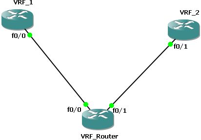
I used following network map:

Both routers "VRF_1" and "VRF_2" are only hosts with only an IP and a default route pointing at the outgoin interface:
VRF1
interface FastEthernet0/1
description Link to VRF_Router
ip address 10.0.100.2 255.255.255.0
speed 100
full-duplex
!
ip route 0.0.0.0 0.0.0.0 FastEthernet0/0

VRF2
interface FastEthernet0/1
description Link to VRF_Router
ip address 10.0.200.2 255.255.255.0
speed 100
full-duplex
!
ip route 0.0.0.0 0.0.0.0 FastEthernet0/1


Now to the routing part:
At first you need an basic VRF lite config:
ip vrf vrf1
rd 1:1
route-target export 1:1
route-target import 1:1
!
ip vrf vrf2
rd 2:2
route-target export 2:2
route-target import 2:2

The two commands route-target export 2:2 and route-target import 2:2 can be summed up with the command "route-target both. In your config this will be automaticaly replaced with to commands shown.

In addition to this there is some IF configuration:
interface FastEthernet0/0
ip vrf forwarding vrf1
ip address 10.0.100.1 255.255.255.0
speed 100
full-duplex
!
interface FastEthernet0/1
ip vrf forwarding vrf2
ip address 10.0.200.1 255.255.255.0
speed 100
full-duplex


The command ip vrf forwarding [vrf_name] associates the IF into a VRF so the traffic is marked up.

Now you need to set up the routing. There for you only need a route for each VRF pointing on the IF and Next-Hop-IP of the targeted VRF.
ip route vrf vrf1 10.0.200.0 255.255.255.0 FastEthernet0/1 10.0.200.2

ip route vrf vrf2 10.0.100.0 255.255.255.0 FastEthernet0/0 10.0.100.2


And thats all. If you issue the command show ip route.
VRF_Router#show ip route
Codes: C - connected, S - static, R - RIP, M - mobile, B - BGP
D - EIGRP, EX - EIGRP external, O - OSPF, IA - OSPF inter area
N1 - OSPF NSSA external type 1, N2 - OSPF NSSA external type 2
E1 - OSPF external type 1, E2 - OSPF external type 2
i - IS-IS, su - IS-IS summary, L1 - IS-IS level-1, L2 - IS-IS level-2
ia - IS-IS inter area, * - candidate default, U - per-user static route
o - ODR, P - periodic downloaded static route

Gateway of last resort is not set

VRF_Router#

You'll see an empty global routing table. If you add show ip route vrf [vrf_name]. As example only the output of one vrf:
VRF_Router#show ip route vrf vrf1

Routing Table: vrf1

[... snip ...]

Gateway of last resort is not set

10.0.0.0/24 is subnetted, 2 subnets
C 10.0.100.0 is directly connected, FastEthernet0/0
S 10.0.200.0 [1/0] via 10.0.200.2, FastEthernet0/1
VRF_Router#

Note that it says explictly which routing table it's showing you and you have one extra routing table for each VRF.


If there are any open questions left, just use the commenting funtion


Regrads,
Zif

Mittwoch, 15. April 2009

DE - VPN on a stick mit Cisco PIX und ASA

Vor einer Weile hat Zif ja die "Router on a stick" Konfiguration gepostet. Ich will die Gelegenheit nutzen, um etwas wesentlich Interessanteres darzustellen, die "VPN on a Stick" Konfiguration auf der Cisco ASA bzw. PIX.

Was bedeutet VPN on a Stick genau, nun es handelt sich dabei um die Konfiguration des VPN so das der VPN Nutzer sich durch das VPN Gateway auf das Internet zugreifen kann. Besonders ist daran, das der VPN Nutzer die Appliance nicht wirklich verlässt sonder direkt über das eingehende Interface wieder hinaus geht. In anderen fällen wird das ganze auch Hairpinning genannt.

Konfiguration.
Zuerst muss das erledigt werden was auf jeder ASA/PIX notwendig ist, also so etwas wie Interface Konfiguration usw.
Grundlegend ist das überall gleich aber unterscheidet sich doch zwischen ASA, PIX und ASA 5505, die Unterschiede werde ich hier posten, aber für genauere Unterschiede werft doch einen Blick auf CISCO.com.

ASA 5510 oder höher

interface ethernet 0/0
description ### Outside Interface ###
nameif outside
ip address 10.255.255.2 255.255.255.0
interface ethernet 0/1
description ### Inside Interface ###
nameif inside
ip address 192.168.0.1 255.255.255.0


ASA 5505

interface vlan 10
description ### Outside Interface ###
nameif outside
ip address 10.255.255.2 255.255.255.0
interface vlan 20
description ### Inside Interface ###
nameif inside
ip address 192.168.0.1 255.255.255.0


PIX

interface ethernet 0
description ### Outside Interface ###
nameif outside
ip address 10.255.255.2 255.255.255.0
no shutdown
interface ethernet 1
description ### Inside Interface ###
nameif inside
ip address 192.168.0.1 255.255.255.0
no shutdown

global (outside) 1 interface
nat (inside) 1 192.168.0.0 255.255.255.0
route outside 0.0.0.0 0.0.0.0 10.255.255.254
! 10.255.255.254 ist der nächste Hop, der Router des Providers

crypto ipsec transform-set ESP-AES256-MD5 esp-aes-256 esp-md5-hmac

crypto dynamic-map DynOutsideMap 100 set transform-set ESP-AES256-MD5
! Konfiguration für den dynamischen VPN Client
!
crypto map OutsideMap 65535 ipsec-isakmp dynamic DynOutsideMap
crypto map OutsideMap interface outside
! Konfiguration der Crypto Map die auf dem Outside Interface gebunden wird

crypto isakmp enable outside
crypto isakmp policy 100
authentication pre-share
encryption aes-256
hash sha
group 2
lifetime 86400


Das ist die Grundlage die fast überall benötigt wird. Als nächstes müssen die spezifischen VPN Parameter konfiguriert werden.


ip local pool POOL_VPN_Client 192.168.1.1-192.168.1.254 mask 255.255.255.0

group-policy GPOL_VPN_Client internal
group-policy GPOL_VPN_Client attributes
split-tunnel-policy tunnelall

tunnel-group GRP_VPN_Client type remote-access
tunnel-group GRP_VPN_Client general-attributes
default-group-policy GPOL_VPN_Client
address-pool POOL_VPN_Client
tunnel-group GRP_VPN_Client ipsec-attributes
pre-shared-key DoNotUseMe


So weit so gut, der Client sollte nun in der Lage sein eine Verbindung zur ASA oder PIX aufzubauen (noch keine wirkliche VPN Verbindung). Es bedarf natürlich noch einen User für die Verbindung. AAA wäre eine Lösung, aber für dieses Beispiel bleiben wir bei der LOCAL Lösung.

username VPNUser password none priv 1

Jetzt etwas interessantes, NAT.
Wir vermuten einfach mal das auf der ASA/ PIX NAT gemacht wird (wird es ja meistens), so muss nun eine NAT Ausnahme konfiguriert werden, damit der VPN Client die internen Hosts erreichen kann.


Object-group network OBJ_VPN_Client
network 192.168.1.0 255.255.255.0
Object-group network OBJ_LAN
network 192.168.0.0 255.255.255.0

access-list NO_nat_inside remark ### NAT exceptions ###
access-list NO_nat_inside permit ip object-group OBJ_LAN object-group OBJ_VPN_Client


So nun sind wir fast durch, noch das NAT Statement hinzufügen.


nat (outside) 1 192.168.1.0 255.255.255.0
! NAT auf dem Outside interface damit der VPN Nutzer eine öffentliche IP
! erhält
nat (inside) 0 access-list NO_nat_inside


Jetzt noch die Standard Regel "Kein Traffic zwischen Interfaces mit dem gleichen Sicherheitslevel" aufheben.

same-security-traffic permit intra-interface


Das war es also!

Ich hoffe es hat gefallen und danke für die Aufmerksamkeit :D

Vollständige PIX Konfiguration

Dienstag, 14. April 2009

EN - VPN on a stick with Cisco PIX and ASA

Well since Zif was doing the "Router on a stick" configuration, I'd like to share with you the much cooler "VPN on a Stick" configuration on the ASA/ PIX.

What does VPN on a stick mean. Well it means that if you connect to a VPN gateway your traffic will run across this gateway and will be forwarded into the Internet (if you try to connect to the Internet). Why is it named "on a stick" this is because you enter the VPN gateway (ASA/Pix) on the
outside interface an you leave it the same way without accessing the private LAN Sometimes it called hair pinning (if you enter an other VPN connection)

So what do we need? First of all an ASA/ PIX and second a VPN Client.

Configuration.
First we´ll have to do some fluff stuff like creating interfaces etc. This is depending on your hardware slightly different. I´ll post the differences here but for later configs please have a look at CISCO.com

ASA 5510 or higher

interface ethernet 0/0
description ### Outside Interface ###
nameif outside
ip address 10.255.255.2 255.255.255.0
interface ethernet 0/1
description ### Inside Interface ###
nameif inside
ip address 192.168.0.1 255.255.255.0


ASA 5505

interface vlan 10
description ### Outside Interface ###
nameif outside
ip address 10.255.255.2 255.255.255.0
interface vlan 20
description ### Inside Interface ###
nameif inside
ip address 192.168.0.1 255.255.255.0


PIX

interface ethernet 0
description ### Outside Interface ###
nameif outside
ip address 10.255.255.2 255.255.255.0
no shutdown
interface ethernet 1
description ### Inside Interface ###
nameif inside
ip address 192.168.0.1 255.255.255.0
no shutdown

global (outside) 1 interface
nat (inside) 1 192.168.0.0 255.255.255.0
route outside 0.0.0.0 0.0.0.0 10.255.255.254
! 10.255.255.254 is the next hop router from the ISP

crypto ipsec transform-set ESP-AES256-MD5 esp-aes-256 esp-md5-hmac

crypto dynamic-map DynOutsideMap 100 set transform-set ESP-AES256-MD5
! configuration for dynamic Clients like the Cisco VPN Client
!
crypto map OutsideMap 65535 ipsec-isakmp dynamic DynOutsideMap
crypto map OutsideMap interface outside
! configuration of the over all Crypto Map that is applied on the outside Interface

crypto isakmp enable outside
crypto isakmp policy 100
authentication pre-share
encryption aes-256
hash sha
group 2
lifetime 86400


Thats the basic part that you need nearly everywhere. Next step would be to configure the specific parameters for your VPN client.


ip local pool POOL_VPN_Client 192.168.1.1-192.168.1.254 mask 255.255.255.0

group-policy GPOL_VPN_Client internal
group-policy GPOL_VPN_Client attributes
split-tunnel-policy tunnelall

tunnel-group GRP_VPN_Client type remote-access
tunnel-group GRP_VPN_Client general-attributes
default-group-policy GPOL_VPN_Client
address-pool POOL_VPN_Client
tunnel-group GRP_VPN_Client ipsec-attributes
pre-shared-key DoNotUseMe


So far, so good, your client should now be able to connect to your ASA or Pix but well, nothing more.
You still need to add a User that is allowed to log in. You could use AAA but for this scenario we stick to LOCAL users.

username VPNUser password none priv 1

Now lets start with the interesting parts
Assuming that you do NAT on your ASA/ Pix you need to configure a NAT exception so that you can access your hosts on the inside interface from your VPN Client.

I tend to use objects groups quite a lot since they enable you to quick change a lot of ACLs. For this reason I´ll set up some object groups and use them later.


Object-group network OBJ_VPN_Client
network 192.168.1.0 255.255.255.0
Object-group network OBJ_LAN
network 192.168.0.0 255.255.255.0

access-list NO_nat_inside remark ### NAT exceptions ###
access-list NO_nat_inside permit ip object-group OBJ_LAN object-group OBJ_VPN_Client


So we are nearly through add a new NAT statement


nat (outside) 1 192.168.1.0 255.255.255.0
! NAT on interface outside so that your VPN User get your public IP
nat (inside) 0 access-list NO_nat_inside


Finlay disable the default rule "No traffic between interfaces with the same security level".

same-security-traffic permit intra-interface


Thats it!

Hope you enjoyed and thanks for your attention.

Full PIX configuration